Power converters
| Website: | Moodle ZČU |
| Kurs: | KEV/EMB Elektromobilita - podklady k výuce |
| Buch: | Power converters |
| Gedruckt von: | Nepřihlášený host |
| Datum: | Montag, 9. November 2026, 00:02 |
Beschreibung
Power semiconductor converters for vehicles with electric or hybrid drive. Traction inverters for supplying the electric motor from the traction battery.
Inhaltsverzeichnis
- 1. Introduction
- 2. Power converters for electric vehicles
- 2.1. Main traction converter
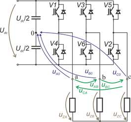
- 2.2. Three-phase voltage-source inverter
- 2.3. Application comparison
- 2.4. Design comparison of inverters for EV
- 2.5. Three-phase inverters for electric drives powered by a traction trolley
- 2.6. Three-phase inverter for traction battery powered electric vehicles
- 2.7. Main parts of electric drive
- 2.8. Switching frequency
- 2.9. Noise
- 2.10. Modern power switches
- 2.11. Power losses
- 3. Other components
- 4. Traction inverter operation within the drive
- 5. Output voltage of three-phase inverters
1. Introduction
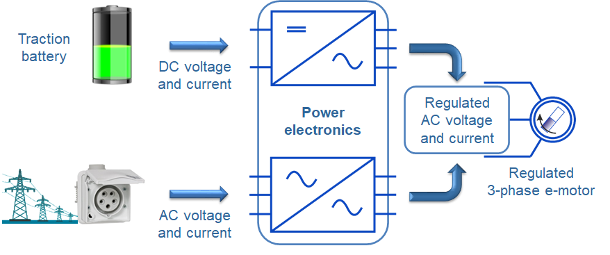
Variable-speed drive
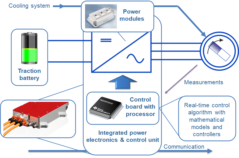
- Variable-speed electric drives always consist of an electric motor, a power semiconductor converter and a control unit with control algorithms.
- The power converter provides a controlled 3-phase voltage (voltage and frequency control).
- Together with the control algorithms, the power inverter provides torque control or higher speed control.
- For electric and hybrid cars, the power converter provides the interface and power transfer between the DC source (traction battery) and the electric motor.
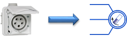
Constant-speed electric drive
- The electric motor is directly connected to a constant voltage and frequency AC source (ie 3f of the mains).
- Constant speed of the stator magnetic flux, unregulated speed, unregulated torque.
2. Power converters for electric vehicles
Main traction converters of electric vehicles - three-phase voltage inverters. Comparison of converters of electric cars and public transport vehicles.
2.1. Main traction converter
Three-phase voltage-source inverter
- The three-phase voltage-source inverter is the dominant type of the main traction converter of electric cars and public transport vehicles.
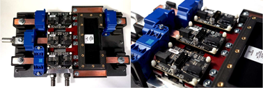
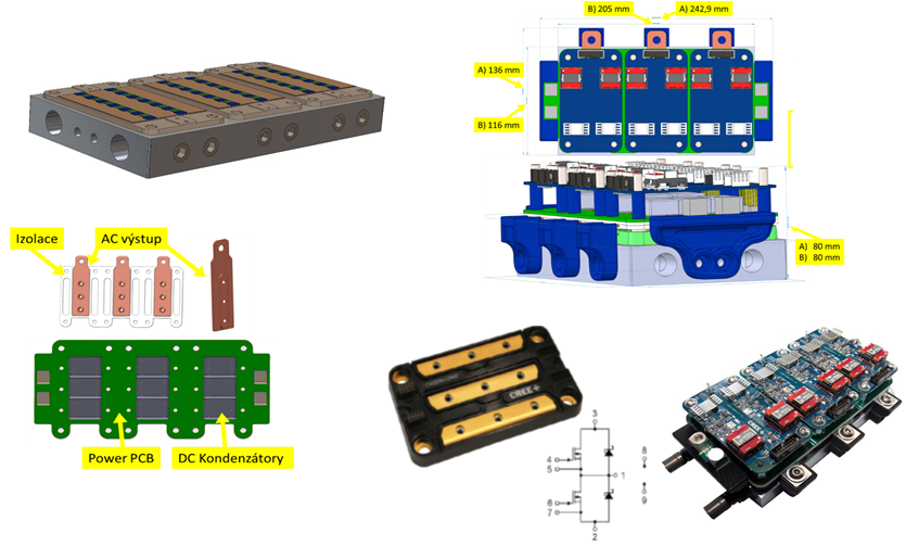
Three-phase voltage-source inverter (CREE SiC), 900 V, 250 kW (RICE FEL/ZČU)
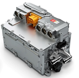
Three-phase inverter for automotive
(Bosch)
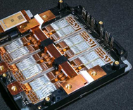
Traction converter (SiC) Porsche Taycan, 800 V
https://www.porsche.com
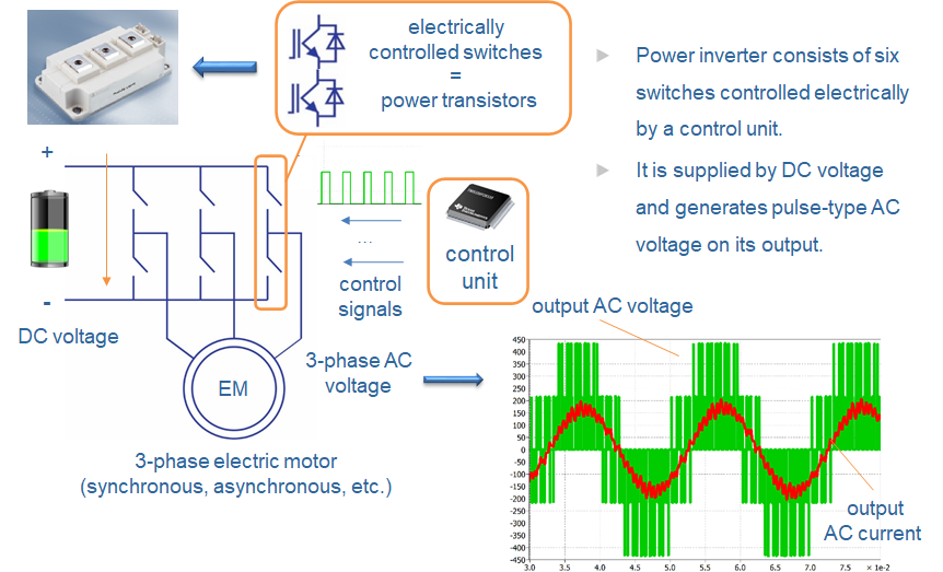
2.2. Three-phase voltage-source inverter
2.3. Application comparison
Public transport vehicles
- Traction trolley power supply - stable (with a certain tolerance) DC voltage
- Large installation space (roof containers)
- Air-cooled inverters
- Modularity
- Noise level requirements: yes, but limited

Trolleybus Škoda 31Tr (250 kW)
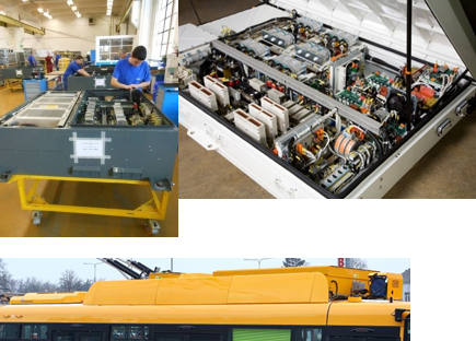
Containers for traction equipment of public transport vehicles
Electric and hybrid cars
- Traction battery supply → significant difference between charged and discharged battery voltage.
- Limited space for drive installation
- Liquid cooling
- Modularity? There is not much space.
- Noise level requirements: high
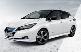
Nissan Leaf (BEV)
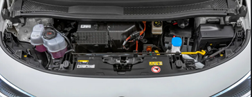
Limited space for drive installation in VW ID.3
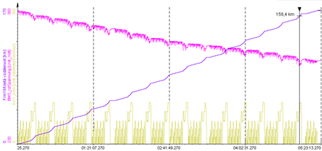
https://www.nissan.cz
https://www.volkswagen.de
2.4. Design comparison of inverters for EV
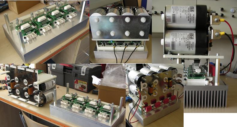
Inverter for public transport vehicles
- IGBT technology
- Air-cooled inverter
- Bulky C filter on the DC side
- Bulky cooler
- The power of the inverter shown in the figure is approx. 10 - 20 kW
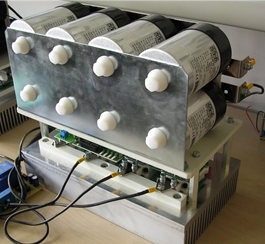
Three-phase inverter for electric vehicles supplied by trolley wire
Traction inverter for electric and hybrid cars
- SiC technology (however, IGBT or MOSFET is still the most widespread technology in electric cars)
- Liquid-cooled inverter
- Small C filter or none
- Small dimensions of the heatsink and the entire inverter (high power density)
- Power up to 200 kW
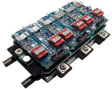
Three-phase inverter for traction battery powered vehicles
2.5. Three-phase inverters for electric drives powered by a traction trolley
2.6. Three-phase inverter for traction battery powered electric vehicles
2.7. Main parts of electric drive
2.8. Switching frequency
Low switching frequency
- High current ripple
- Low current quality (harmonic distortion)
- Additional losses
- Noise
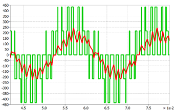
Load voltage and current - low switching frequency
- Small current ripple
- High current quality - low harmonic distortion
- High efficiency
- Noise reduction
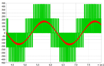
High switching frequency

2.9. Noise
Magnetostriction
- Magnetic field tied with the switched current causes mechanical oscillations in all magnetically conductive materials.
- Mechanical
oscillations generate noise corresponding to the switching frequency.
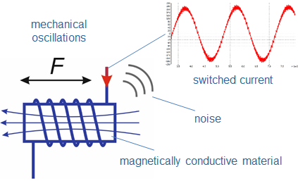
- Switching frequency above 20 kHz is not audible. The upper limit depends on age.
- Standard IGBT technology:
- For power of 100 kW is the switching frequency above 20 kHz practically not achievable (switching losses to high).
- High
switching frequencies achievable with SiC
technology.

2.10. Modern power switches
Blocking voltage
- IGBT: < 6500V
- Si MOSFET: < 950V
- SiC MOSFET: < 3300 V
- GaN: < 650V
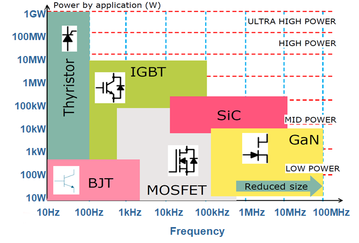
- Increase in blocking voltage and rated current
- Increase in switching frequency
- Decrease in losses
- Size reduction
2.11. Power losses
Example of a 100 kW converter
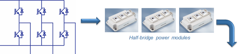
- The inverter consists of six switches, ie three modules - half-bridges.
- Each module produces 700 W losses.
- A 100 kW inverter with 98% efficiency produces 2 kW of power output.
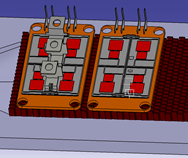
- Losses must be diverted from a very small area of the chip.
- Thermal resistance and heatsink temperature are key factors.
- Water cooling offers the optimal solution.
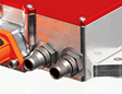
https://www.brusa.biz
3. Other components
Sensors, control HW, control SW.
3.1. Sensors
- Voltage sensors
- Current sensors
- Rotor speed / position sensors
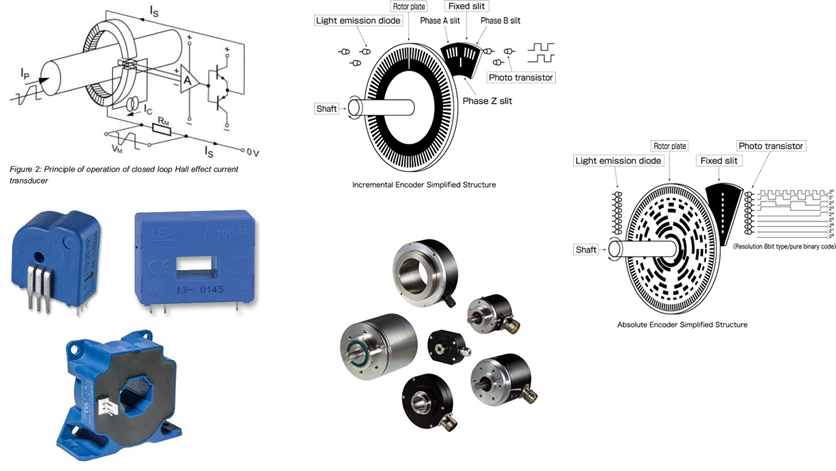
www.sensimatech.com
https://www.brusa.biz
3.2. Control HW
- Control microcontrollers designed to control electric drives and power converters (eg Texas Instruments TMS320F28xxx)
- Peripherals adapted for these applications
- ADC
- PWM, dead time units
- QEP
- ...

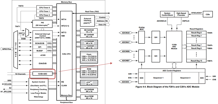
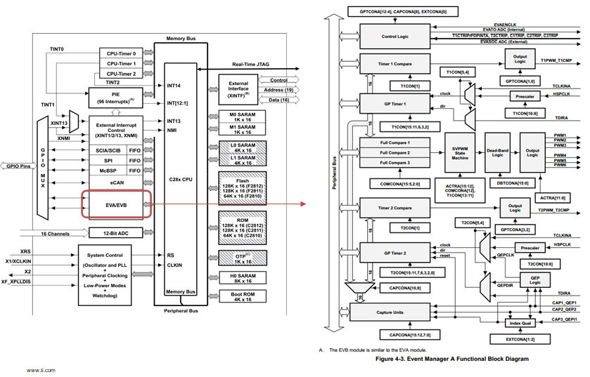
Texas Instruments TMS320F28xxx microcontroller for controlling drives and power converters and its peripherals (PWM peripherals detail)
3.3. Principle of control algorithms
- Proper operation of the whole system is strongly dependent on the position/speed sensor.
- Special attention is paid to sensorless methods, but they still suffer by poor performance at very low speeds.
- Sensorless techniques are used for fault diagnostic (sensor data validation).
- The control algorithm has crucial impact on drive performance and effectivity – it makes the drive unique.
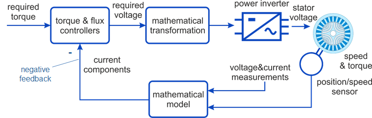
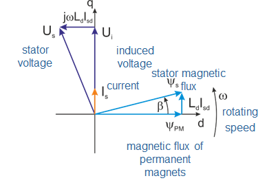
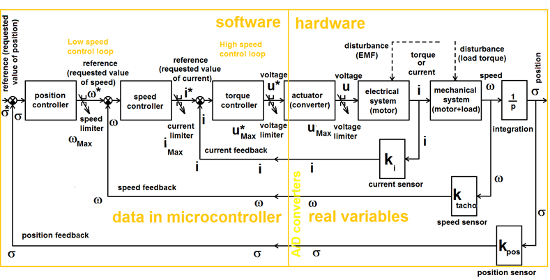
3.4. Cascade structure of drive control
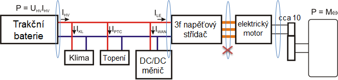
4. Traction inverter operation within the drive
Acceleration, motor and generator mode, torque characteristics of induction machines, traction characteristics of a drive.
4.1. Start-up
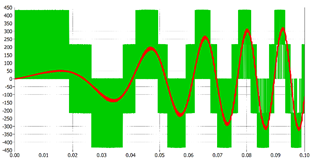
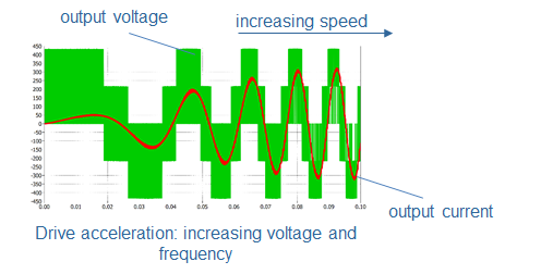
Voltage and current (single phase) of a motor supplied by a three-phase inverter during start-up of the drive
4.2. Drive in motor and generator mode
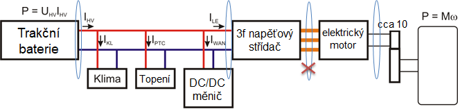
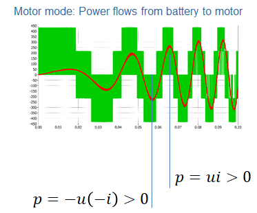
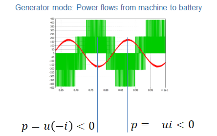
4.3. Voltage and frequency change for induction machine
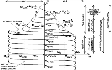
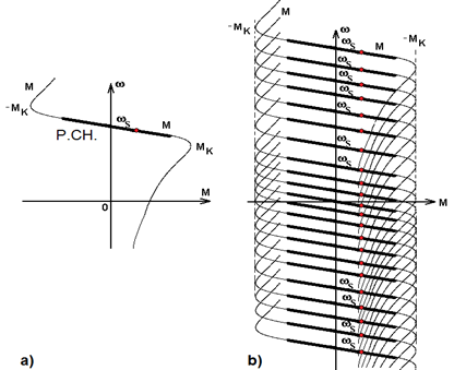
Torque characteristics of induction machine
4.4. Drive characteristics
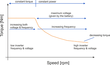
Torque-speed characteristic of regulated electric drive
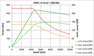
Torque and power of PMSM
4.5. Influence of battery voltage drop
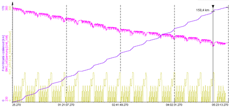
Voltage drop during traction battery discharge
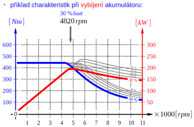
Influence of battery discharge on torque and power
5. Output voltage of three-phase inverters
What voltage do we have available on the AC side of the traction converter at a given traction battery voltage? How can the drive control maximize the output voltage?
5.1. Basic variables
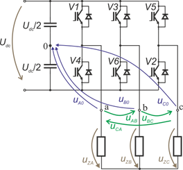
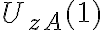
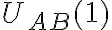
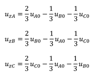
Output voltage
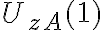
 phase voltage of the inverter
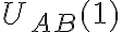
 phase voltage of the load
 phase-phase voltage
- For the 1st harmonic component:
 … viz KEV/PVE2

Example
- Battery voltage \ (U_ {dc} = 400 V \), what is the available voltage on the motor?
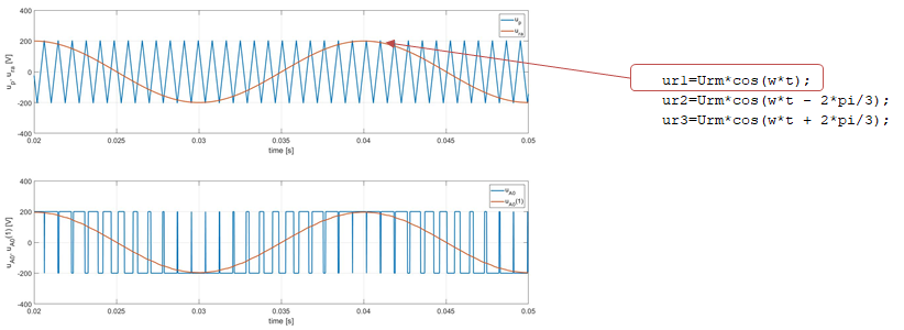
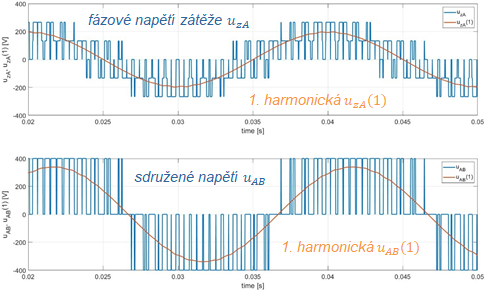
5.2. Sinusoidal PWM
Maximum of the 1st harmonic
 : U_dc/2=400/2=200
V (rms value
141 V)
 : U_dc/2=400/2=200
V
(rms value
141 V)
 : U_dc/2 √3=400/2 √3=346 V (rms value
245
V)
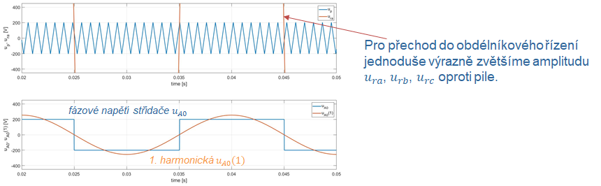
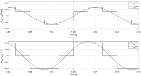
5.3. Square-wave control
Maximum of the 1st harmonic
 ,
- i.e. rms value of the 1st harmonic: 180 V,
- rms value of the square-wave voltage : 200 V
 ,
- i.e. rms value of the 1st harmonic: 180 V,
- rms value of the square-wave voltage : 189 V

- i.e. rms value of the 1st harmonic: 312 V,
- rms value of the square-wave voltage : 326 V
5.4. Voltage increase by zero-sequence component - principle
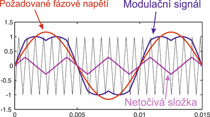
- Non-rotating components can be used to increase the output voltage of the inverter.
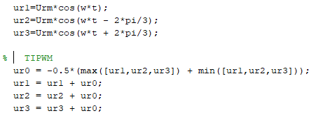
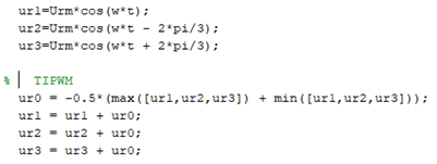
- Vector PWM (SVPWM) and PWM injecting the 3rd harmonic or sawtooth signal (TIPWM) work with the non-rotating component.
- Both SVPWM and TIPWM lead to an equivalent output voltage - both modulations actively inject a non-rotating component in the form of a sawtooth signal.
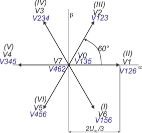
Basic inverter voltage vectors for SVPWM
TIPWM (triangular signal injection PWM)
5.5. Voltage increase by zero-sequence component - example
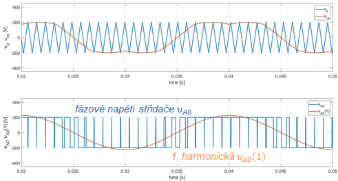
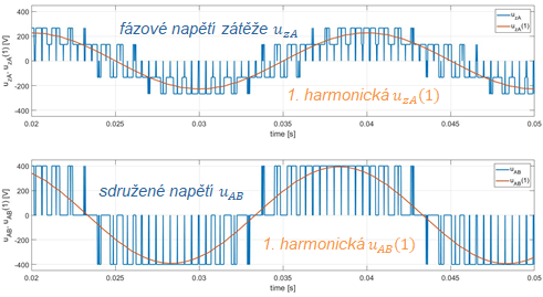
Maximum output voltage – SVPWM a TIPWM
- Hexagon inscribed circle:

- : 231 V, 163 Vrms
- :
231 V, 163 Vrms
- : 400 V, 283
Vrms
5.6. Summary
Example
Battery voltage \ (U_ {dc} = 400 V \), what is the available voltage on the motor?
|
Control |
|
|
|
|||
|
max |
rms |
max |
rms |
max |
rms |
|
|
Sinusoidal PWM |
200 |
141 |
200 |
141 |
346 |
245 |
|
TIPWM |
231 |
163 |
231 |
163 |
400 |
283 |
|
SVPWM |
231 |
163 |
231 |
163 |
400 |
283 |
|
Square-wave control |
255 |
180 |
255 |
180 |
441 |
312 |