Charging
| Stránky: | Moodle ZČU |
| Kurz: | KEV/EMB Elektromobilita - podklady k výuce |
| Kniha: | Charging |
| Vytiskl(a): | Nepřihlášený host |
| Datum: | pondělí, 9. listopadu 2026, 16.19 |
Popis
Methods of charging electric vehicles.
Obsah
- 1. Cell charging
- 2. Recharging by recuperation
- 3. Charging from AC power grid
- 4. Fast DC charging
- 5. Connector types for EV charging
- 6. CCS standard
- 7. Charging socket placement
- 8. Example of charging services (E-On)
- 9. Charging infrastructure in ČR
- 10. Wireless charging
- 11. Safety
- 12. Traction battery replacement
1. Cell charging
- Charging current lower than discharging (e.g. 10x, 20x, etc.).
- Lithium ions Li + must intercalate into the graphite layers → it limits the charging speed.
- By charging, we transfer the cell to an unstable state.
- The total charging current
 is given by
- difference between the charging voltage and internal voltage,
- the size of the internal resistance
 .
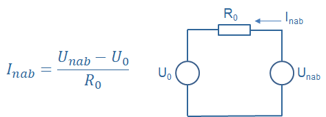
- Charging increases the battery voltage.
- By simultaneously increasing of
 , we maintain a constant charging current = constant current charging (1st charging step).
- However, the maximum cell voltage must not be exceeded.
- If reaches the maximum level (
 ), the voltage does not increase further and is constant = charging with constant voltage (2nd charging step, so-called saturation part).
- The charging current decreases exponentially => this charging is time consuming.
- Manufacturers often publish charging time needed to reach 70-80% capacity.
- Maximum cell voltage depends on technology:
- usually 4.2 V for Co, Ni, Mn, Al.
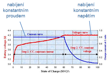
Li-ion battery charging
- The cell charging current is usually recommended to be 0.5-1C.
- To increase the battery service life, small charging currents are recommended.
- In parallel, do not charge to full SoC (e.g. do not start the saturation part) → reduced voltage stress.
- High charging currenta speed up the first part, but prolongs the saturation part.
1.1. State of charge
- State of Charge (SoC) is practically impossible to determine according to the current voltage.
- It is possible according to the open circuit voltage (OCV) voltage for the given temperature → in steady state, i.e. enough time after unloading.
- SoC is usually estimated by counting the charge:

- However, good accuracy of the current measurement must be ensured.
- Overcharging is not possible - Li-ion will not take over another charge, charging must be stopped, otherwise safety is endangered.
1.2. Battery aging
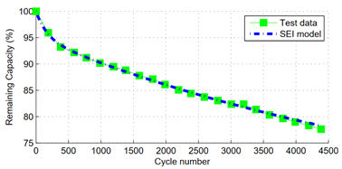
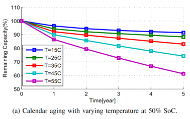
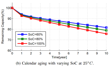
- The aging of the battery results in a gradual reduction in capacity.
- Symptoms:
- capacity reduction,
- internal resistance increase,
- shortening of the 1st charging step (= constant current charging),
- extension of the saturation part (= constant voltage charging).
1.3. Battery lifetime extension
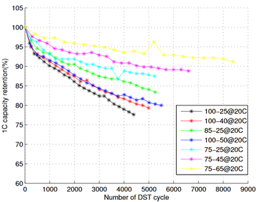
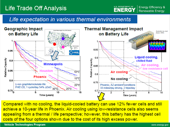
- Ensure a suitable temperature - ideally around 20 ° C (high temperatures harm more than low temperatures).
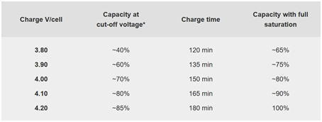
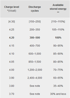
- Limit the size of the window used - do not charge to 100%, avoid deep discharge.
- Limit the maximum charging voltage.
- Limit charging current - frequent use of fast charging significantly speeds up battery aging.
Low temperature
- Charging Li-ion below 5 ° C by limited current, charging in frost is not allowed.
- Fast charging in the range of 5 - 45 ° C, but preferably 10 - 30 ° C.
- Charging in the cold damages the battery ("plating" the anode with lithium, permanent, irreversible changes).

High temperature
- High temperatures are not good for any type of battery.
- Batteries are usually not charged at T> 50 ° C to avoid accelerated aging.
- Limit charging current, charging with high current at high temperature reduces the capacity of the battery. Moreover, it may cause gas production and inflation.

https://www1.eere.energy.gov
2. Recharging by recuperation
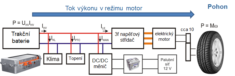
The vehicle's kinetic energy is used to recharge the battery by the recuperation. The electric drive is in generator mode, where the electric machine is controlled as a generator and the vehicle is braked. Power is taken from the electric machine, which is then used to recharge the battery.
Charging by the recuperation can be used for
- traction battery charging (Li-ion, Li-pol, Ni-MH, etc.),
- HEV, PHEV, BEV,
- on-board lead acid battery (12 V) charging,
- especially µHEV: start&stop + ESM (Energy Smart Management).
Driving mode
Braking mode (recuperation)
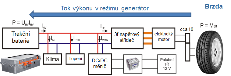
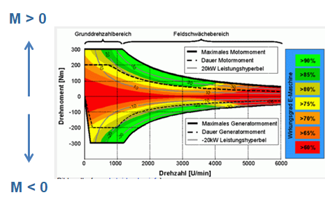
- During braking, the polarity of the torque changes compared to the drive mode. This changes the polarity of the mechanical power and recharges the traction battery.
-
Driving mode

Braking mode

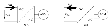
Change of current polarity on the DC side of the drive (traction battery side)
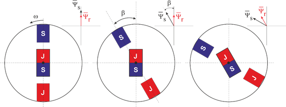
Motor vs. generator mode for electric synchronous machine with permanent magnets
- Rated power of the machine in motor and generator mode is practically the same.
- However, the rated charging current of the cell is about 10 times smaller than the rated discharging current!
- => Charging power is less than power of the generator or the battery must be oversized in terms of discharge current.
- Remaining braking torque must be provided by mechanical brakes.
- Often, recharging power is limited by battery management (BMS),
depending on set limits or battery condition (cell disbalancing,
temperature, etc.).
https://www.hybrid-autos.info
3. Charging from AC power grid
Charging the traction battery of electric or hybrid vehicles from the AC power grid. Single-phase and three-phase charging via on-board chargers or traction converter.
3.1. Charging from single-phase ac power grid
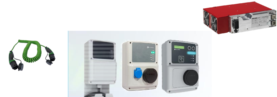
- Charging from standard household sockets or charging stands
- Paremeters in ČR: 230 V, 50 Hz, 16 A
- Power:
 (estimated power factor)
- The current can be increased using the wallbox.
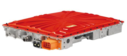
- The on-board charger converts the AC voltage and current from the household power grid to the DC voltage and current of the battery needs.
- At the same time, the BMS communicates with the charger.
- Be aware of long extension cables; on-board charging systems usually monitor the connection impedance.
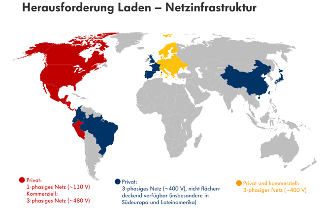
- However, the hosehold socket voltage varies in different parts of the world.
- In case of 110 V is the power 1600 W only (at the same current of 16 A).
https://www.brusa.biz
3.2. Charging from three-phase ac power grid
- Charging from standard household sockets or charging stands
- Parameters in ČR: 3x 400 V, 50 Hz, 16 A, alternatively 32 A in industrial plants
- Power:
- a)

- b)

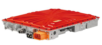
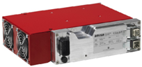
- The on-board charger converts ac voltage and current of the household socket to the dc voltage and current of the battery.
- At the same time, the BMS communicates with the charger.
3.3. Charging time from ac power grid
|
Charging type |
Power |
Approx. charging time |
|
single-phase, 16 A |
3 kW |
5 h / 100 km |
|
single-phase, wallbox 40 A |
9 kW |
1,6 h / 100 km |
|
single-phase, 16 A |
10 kW |
1,4 h / 100 km |
|
three-phase, 32 A |
20 kW |
50 min / 100 km |
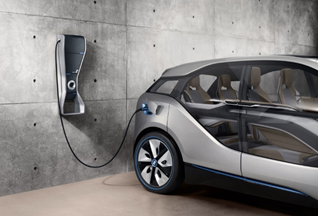
Wallbox BMW 1x 230 V, 40 A
https://www.brusa.biz
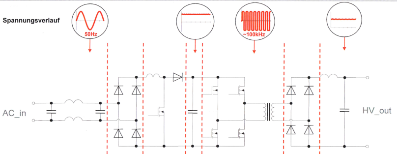
3.4. Topology of on-board charger
Topology of on-board charger with galvanic isolation
3.5. Charging via traction converter
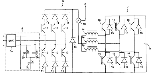
- The traction power converter (of power usually > 100 kW) can be used for charging, instead of the on-board charger.
- Renault ZOE, C-Zero (patented as Renault Chameleon system)
- 3x 400 V, 63 A, up to 43 kW, charging speed approx. 25 min / 100 km
4. Fast DC charging
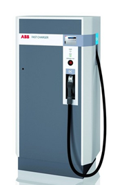
- Unlike AC charging, the charger is not located in the vehicle during DC charging.
- The conversion of the ac voltage and current into the dc quantities is ensured by an external charging station.
- The DC voltage of the charging station is directly connected to the traction battery terminals.
- The BMS is communicates with the charging station and sets the voltage level.
- The external installation of the charging station enables to design the charger for significantly higher power rates.
- Outputs of tens to hundreds of kW (power of 150 kW is wide spread, actual maximum power up to 350 kW)
- The charging time is significantly shortened (about tens of minutes to just several minutes).
- However, fast charging also has disadvantages, in particular
- large charging losses yielding costs,
- shortening battery life (loss of capacity),
- higher price per kWh.
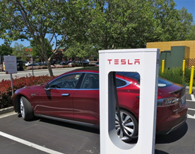
- The actual condition of the battery when arriving to the charging station greatly affects the charging speed.
- Actual charging speed mainly depends on
- temperature,
- cell disbalancing.
- Based on these parameters, battery management determines the charging speed.
- Charging speed is slower when intensive cell balancing is needed.
- In addition to the temperature, the charging speed is therefore determined by the driving style.
- Nonaggressive drivine at favorable temperatures → fast charging.
- Aggressive driving (accelerations and braking), unfavorable temperatures → charging power does not reach the power rate of the charging station.
www.tesla.com
5. Connector types for EV charging
AC charging
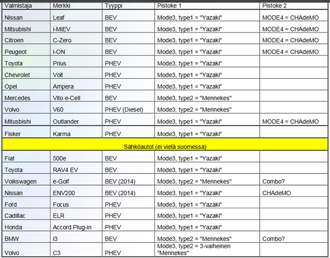
Type 1 - Yazaki
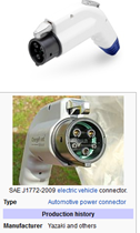
Type 2 (AC) Mennekes
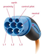
Fast DC charging
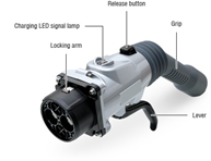
Combo (CCS) 1
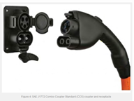
Combo (CCS) 2
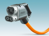
Tesla

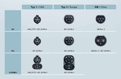
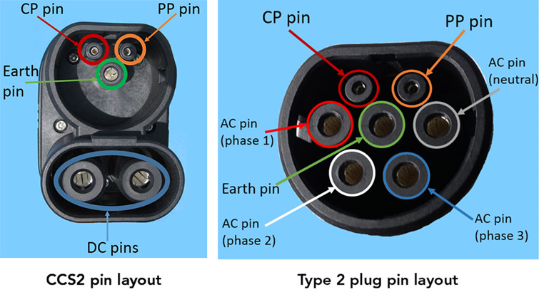
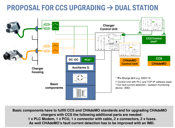
- Usually, single fast dc charging station includes more than one type of the connector.
https://phoenixcontact.com
en.wikipedia.org
https://thedriven.io
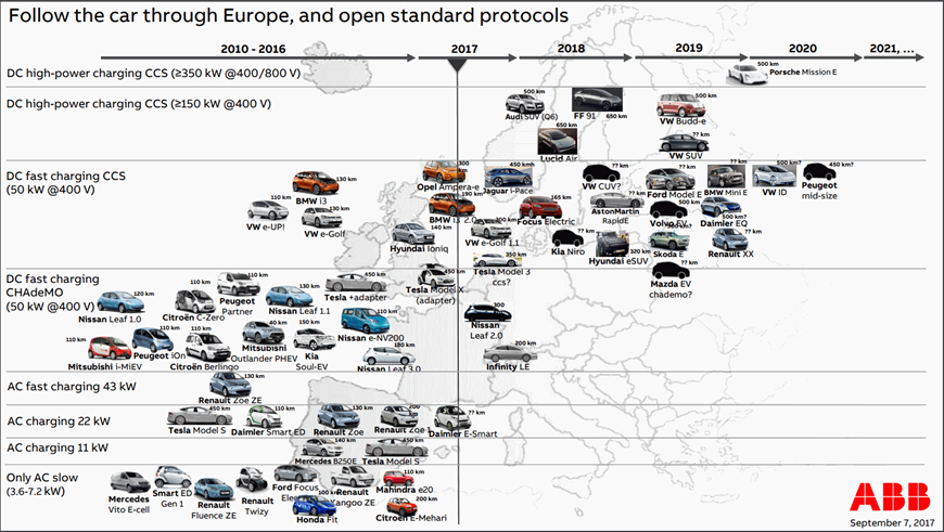
6. CCS standard
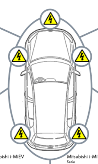
7. Charging socket placement
8. Example of charging services (E-On)
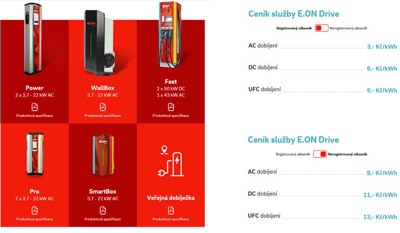
Price list for AC and fast DC charging on public charging stations (E-On)
9. Charging infrastructure in ČR
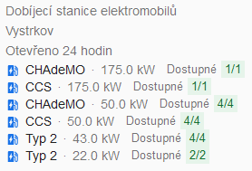
The largest charging station in the Czech Republic
- Charging station of the E-On company in Vystrkov (D1 highway, exit Humpolec)

Distributor networks
- The networks of charging stations are operated by all three electricity distributors (ČEZ, E-On, PRE), Tesla and others.
- 480 charging stations in 2019

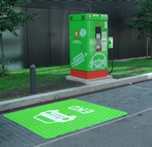
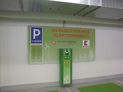
Public AC charging station of the ČEZ company
nabijto.cz
10. Wireless charging
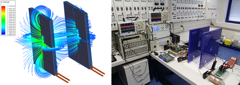
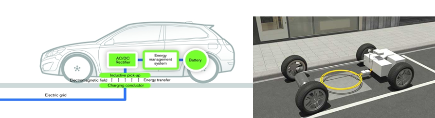
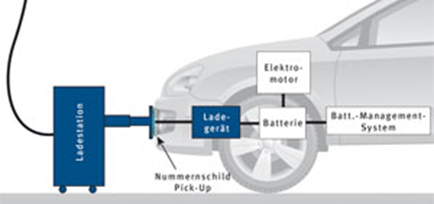
- Wireless power transfer between two planar coils.
- The coils completed by capacitors build a resonance circuit.
- The highes effectivity is reached whed the system operates at the resonant frequency.
-
Resonant frequency: hundrets of kHz.
-
The power transfer achieves high efficiency (> 90%).
https://passive-components.eu
https://www.theengineer.co.uk
11. Safety
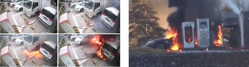
Basic rules
- Shorten length of power connection - Avoid long extension cables.
- Be aware of high temperature conditions.
12. Traction battery replacement
- Instead of recharging the battery in the vehicle, the standardized traction battery is removed and replaced by a charged one.
- The removed batteries are then charged, usually under ideal conditions (optimal temperature and charging power).
- This can significantly extend battery life.
- The battery replacement system is suitable for electric vehicle fleets (e.g. delivery system).
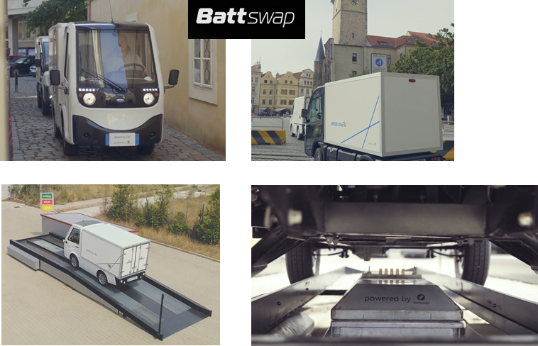
Delivery service in Prague with a battery replacement system
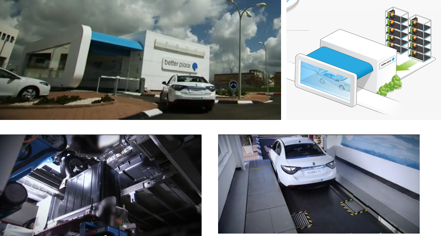
Car battery replacement system (no longer active)
BetterPlace.com