
Hybrid cars
Completion requirements
Passenger cars with hybrid drive, where the drive consists of a combination of a traditional internal combustion engine and an electric motor.
2. Types of hybrid drives
2.1. Serial hybrid drive
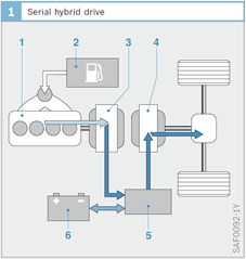
1 – ICE
2 – fuel tank
3 – electric machine (generator)
4 – electric machine (motor)
5 – power inverter
6 – battery
- Serial connection of acceleration force sources.
- The series arrangement consists of an internal combustion engine (ICE) and a pair of electrical machines.
- The internal combustion engine (ICE) is not mechanically coupled to the axle.
- The electric machine (3) works as a generator.
- All power flow to the axle is realized through an electric machine (4).
- The electric machine (4) is working
- as a motor in drive mode, energy is taken from the traction battery and ICE,
- as a generator during braking, the traction battery is charged,
- as ICE starter.
Drive mode

 ,

 ,

Brake mode
- ,

- ,


- ICE can be operated at the optimal efficiency point:
 = konst. =
 .
- ICE is not mechanically coupled to the axle → many installation options in the car.
- Low power transfer efficiency from ICE to wheel (large number of conversions).
Example
- Maximum efficiency

- Buses in city traffic, ie. stop & go driving style on a known route.
- Range extenders - practically BEV, emergency driving after discharging the battery.